Where It All Begins: Why Structure Should Lead Aircraft Conceptual Design
- John Courter
- 15 hours ago
- 15 min read
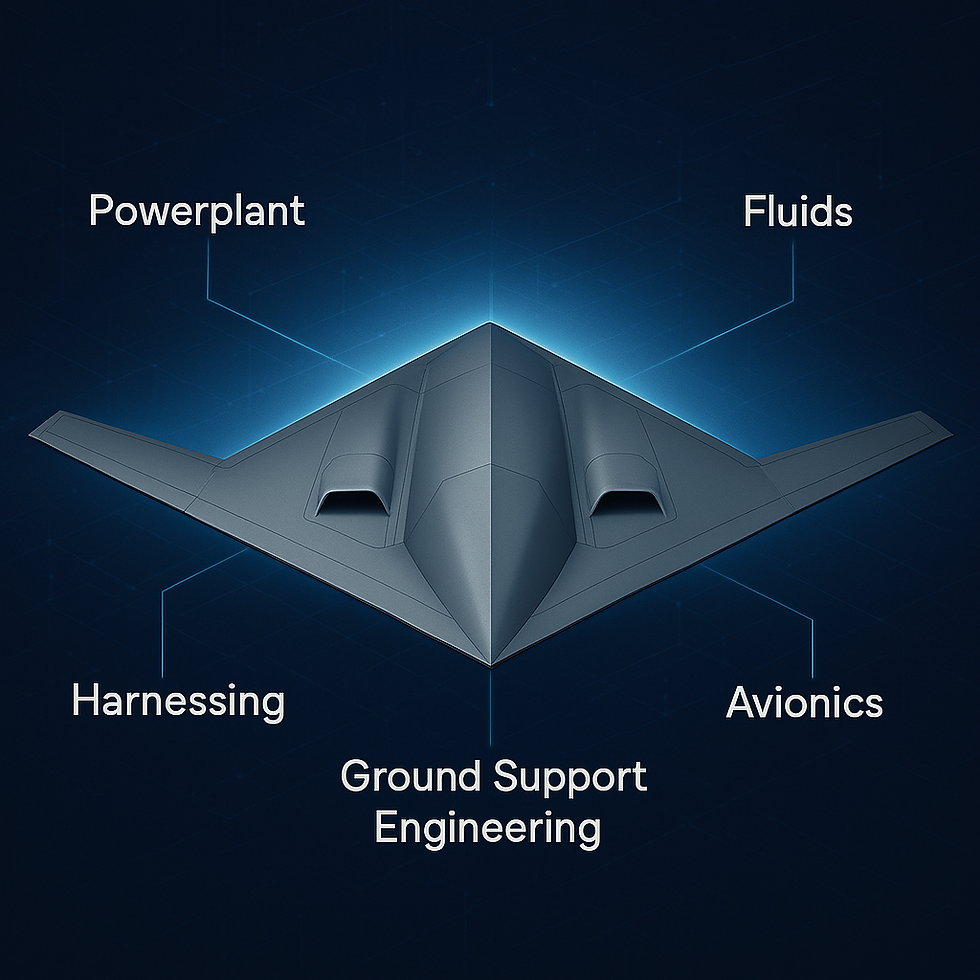
After a short break, we’re back with another installment of the Angels Aircraft blog series, diving deeper into the new space approach—how to build faster, cheaper, and scalable systems for mass manufacturing. Today’s topic is especially close to my heart: Structures. With much of my academic background and professional experience rooted in structural design, I believe this is where vehicle conceptual design should begin. In most cases, starting with structures leads to the most cost-effective solutions when viewed through the lens of design for manufacturing.
Why Start with Structures?
Starting with structures makes sense because structural design inherently defines the vehicle's integration framework—it supports and constrains every other technical subsystem. It’s not just about carrying loads; the structure determines what’s physically possible and what trade-offs can be made across the design.
In my previous roles, I often saw structural teams forced to retrofit a vehicle around a vision crafted by conceptual designers or business development engineers—visions that didn’t always account for what structures could realistically deliver. Sometimes the engines demanded more thrust than the airframe could support. Other times, the fuel volume didn’t fit, or the thermal environment exceeded what standard materials could handle. These are avoidable problems—if structure leads the conceptual design.
Of course, structure-first doesn’t mean structure-only. This is a systems engineering approach. You start with a structurally sound concept, then iterate: check with propulsion, avionics, fluids, and systems teams. Get their input. Adjust the structure. Repeat. The goal isn’t to make every decision in isolation, but to use structure as the foundation for smart design trades that lead to a more affordable, manufacturable vehicle.
For the purposes of this blog series, we’ll focus on composite structures. While I’ll note some caveats for metallics and other material systems, we’re designing an aircraft—we're aiming for light, optimized, and efficient.
Key Structural Considerations
1. Unitization Use as few parts as possible—without making the cost of failure too high. Composites shine here. You can design complex geometries that reduce assembly burdens. But that complexity needs to be controlled.
2. Layup Simplicity The layup should be achievable with a single tool, and simple enough that a reasonably trained composite technician can understand and execute it. Avoid negative draft angles. Zero-degree drafts are acceptable only if cross-sections are constant and you’re using a tooling material with a high coefficient of thermal expansion (CTE). Uniform thickness and cross-section help too. Exceptions exist, of course—but they drive up cost.
3. Tooling Strategy Smart tooling is great but comes with cost and expertise requirements that may not scale. Multi-piece tools mean more time in setup, breakdown, and alignment. For early development, especially prototyping, keep it simple. Start with hand layup and cured systems to prove functionality before moving into production-level tooling.
Meeting Your Specifications
Before diving into detailed design, it’s critical to define the broad goals of your platform and outline your target mission profiles. You should have a rough idea of the payload weight, the distance it needs to travel, the speed it must maintain, and what functional objectives must be achieved during the mission. These parameters guide everything else that follows.
From there, establish a trade space—a framework that balances three fundamental components: cost, schedule, and technology. These elements are inherently linked. I often refer to the materials engineering ternary phase diagram as a useful mental model here: prioritizing one area inevitably comes at the expense of the others. For example, a budget-focused design might sacrifice technological advancement or require a longer development timeline. Likewise, pushing advanced technologies or aggressive schedules will drive up costs.
To inform your trade space, benchmark cost-per-pound metrics across various platforms:
Commercial aircraft: ~$500–$800/lb
Military aircraft: >$3,000/lb (some exceeding $10,000/lb)
High-performance automotive: <$100/lb, up to ~$1,000/lb ceiling
Your mission package should also define approximate volume and location constraints. Ideally, components should be arranged to maintain a neutral center of gravity. Similarly, your engine selection and efficiency will directly drive fuel requirements, which in turn impact structural and volumetric layout.
Once you’ve established these baseline parameters, the next phase is cross-functional: bring in propulsion, avionics, fluids, and other technical teams. Their input is critical—they should be engaging in the same trade space logic as the structural team. Structurally driven design doesn’t mean working in isolation—it means setting a solid foundation from which smart trade-offs can be made collaboratively.
Avionics Harnessing
Designing the avionics harnessing system is a critical balancing act. The goal is to minimize wiring complexity and weight while still collecting the data needed to sense and respond to the environment effectively.
There are two primary approaches:
Analog systems, where distinct voltages and signals are transmitted separately, often with limited compression.
Digital systems, which allow for significant data compression and multiplexing—transmitting multiple signals over a single wire.
In most designs, power and signal lines must be kept isolated. A key early decision for any program is whether to adopt a fully digital architecture. Going digital can dramatically reduce harness weight and complexity, but it also requires more upfront integration effort and digital interface standardization.
Another important consideration is power distribution. Heavier, isolated power lines should not be routed all the way from the flight computer to every subsystem. At Angels Aircraft, we favor a regionalized power and data approach:
Long-distance data and power backbones run across the airframe (e.g., left wing, right wing, fuselage).
Local breakout lines serve specific systems within each region.
This minimizes overall harness weight and complexity.
We also prioritize the use of commercial off-the-shelf (COTS) connectors—simple, readily available, and proven—over custom-designed, complex connectors that can drive up cost and complicate maintenance.
Your avionics harnessing strategy must be tightly integrated with the structure, which provides the physical routing paths for all harnesses. In a scaled manufacturing context, harness supports should be integrated into the structure itself—either molded in or machined features—rather than added post-production. While on-site bonded or adjustable supports offer flexibility during prototyping, they introduce unacceptable variability for high-rate production.
I often look to automotive design for inspiration—not because those solutions can be directly copied for aircraft, but because the automotive industry has undergone vast amounts of iteration at scale. It’s a great reference point for harnessing techniques, connector types, attachment strategies, and support methodologies.
Once the overall avionics layout is defined, the avionics team should be given enough freedom to route their systems, wires, and components effectively. Structural keep-out zones should be established early to ensure routing paths remain viable throughout the design process.
Fluids
The fluid systems architecture—encompassing actuation, fuel storage, and routing—is one of the most foundational elements of aircraft design. Much like avionics, key decisions must be made early, as they cascade through structural integration, system performance, and overall manufacturability.
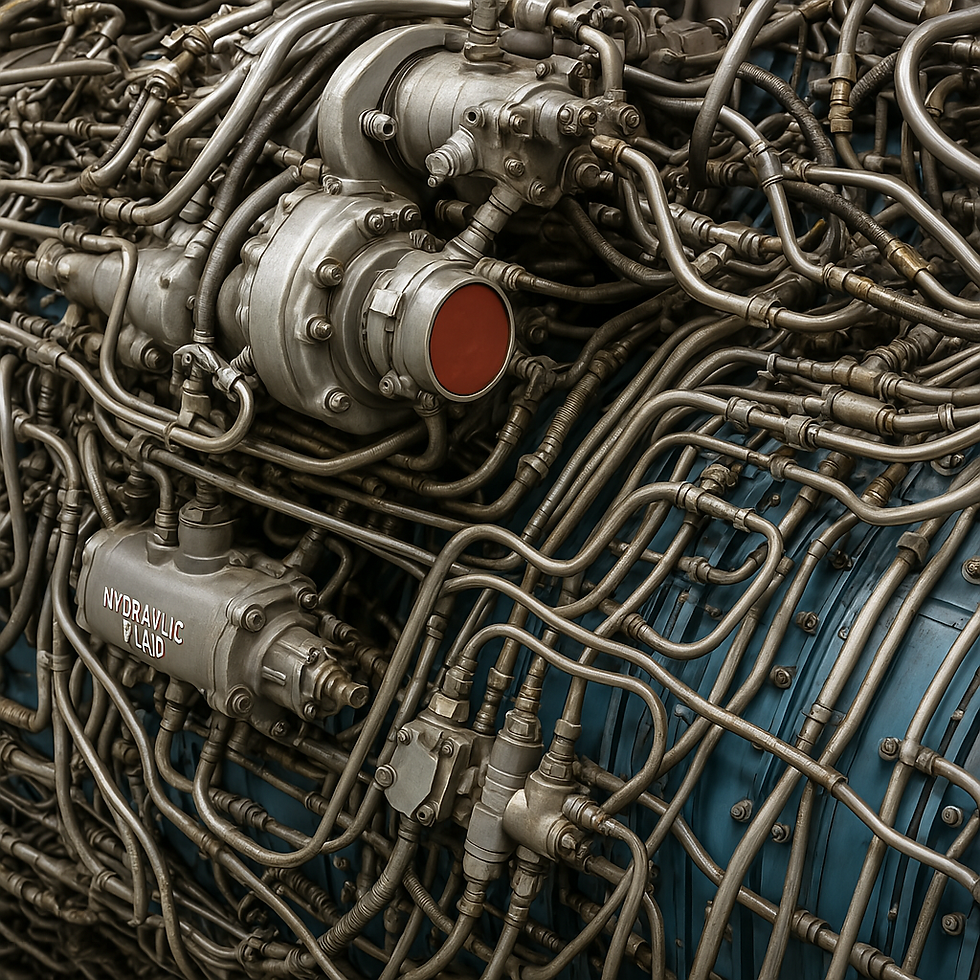
Actuation: Hydraulic vs. Electric
One of the earliest choices involves determining how the vehicle’s control surfaces will be actuated. Traditionally, hydraulics have been the industry standard, delivering high force density and rapid response across countless legacy systems. However, hydraulic systems come with significant complexity: they require a network of fluid lines, actuators, reservoirs, and pressurization systems, all of which contribute to added weight, maintenance overhead, and packaging constraints.
On the other hand, electrically actuated systems—now increasingly common in modern aerospace—eliminate the need for hydraulic plumbing. They instead rely on onboard power generation and electric motors, often resulting in higher component weight but offering simpler integration, better modularity, and reduced servicing requirements. Choosing between these two systems must tie directly into the overall trade space, weighing performance needs against weight, complexity, and cost. At Angels Aircraft, we continually anchor these decisions to our dollars-per-pound target for scalable manufacturing.
Fuel System Architecture
Beyond actuation, fluid systems become even more critical when fuel enters the equation. The type of fuel used—and how it's stored, routed, and isolated—has a deep influence on material selection and vehicle architecture.
First, fuel compatibility must be addressed. It’s a common but dangerous assumption that most materials, particularly composites, are fuel-tolerant by default. While cured composites are chemically stable in most environments, they can still absorb and degrade when exposed to certain fuels, especially organic solvents. In these cases, internal barrier layers or liners may be required to reliably isolate the structure from long-term chemical exposure. This consideration alone may eliminate certain structural materials from contention and should be evaluated early in the design process.
Fuel system access also depends heavily on the platform’s intended life cycle. For reusable platforms with long service intervals, fuel tanks must be accessible for inspection and maintenance. Conversely, in the case of low-cost or attritable systems, it may be acceptable to seal the tanks entirely—designing for limited reuse or single-mission lifespans, with access provided only for critical mechanical components.
While ancillary needs like fill ports, drains, and sampling access are relatively minor at the conceptual stage, they shouldn’t be overlooked. Their placement will influence packaging, ergonomics, and field servicing protocols.
Routing and Integration
Once propulsion systems and actuation methods are selected, fuel routing can be mapped. Like avionics harnesses, fuel lines require thoughtful planning: routing paths must avoid high-heat zones, accommodate maintenance access, and preserve structural integrity. This is where integration with the structure becomes critical.
Support and connection points for fuel lines should be built into the structure from the outset. These features not only secure and protect the routing but also serve as anchor points for scalable manufacturing. While temporary, bonded-in-place supports might be acceptable for prototypes, they introduce variability and rework that can cripple efficiency in high-rate production. Fixed supports—molded or machined into structural elements—are the preferred approach when designing for volume.
By this point in development, the conceptual designer should already have a clear sense of how fuel will be stored. Will it be integrated into the wings? Housed in a fuselage bladder? Distributed through a flying wing structure or centralized in a wing box? Each architecture comes with its own constraints, and understanding them early will steer not just structural layout but also the platform’s overall volumetric efficiency.
Fueldraulics: A Hybrid Approach
As a final consideration, there's an opportunity to borrow from rocketry in the form of fueldraulic systems—where fuel, rather than hydraulic fluid, is used to power actuators. This approach is particularly useful in vehicles where actuation occurs near the propulsion system and at least one engine is assumed to be running during control input.
Fueldraulics eliminate the need for separate hydraulic reservoirs and fluid types, simplifying the system. However, they introduce their own design complexities. Routing must prevent fuel entrapment and ensure proper flow throughout the system. Seal integrity becomes even more critical, as actuators must perform reliably over the life of the platform while exposed to the operating fuel. For applications like thrust vectoring or backup control systems, fueldraulics offer an elegant solution worth considering in the concept architecture phase.
Powerplant
Selecting a powerplant is one of the most critical decisions in the aircraft design process. The propulsion system influences not only performance and weight but also fuel requirements, integration complexity, and lifecycle cost. At Angels Aircraft, we treat the powerplant as either the primary or co-primary design driver alongside the structure—often trading places in importance depending on the mission and configuration.
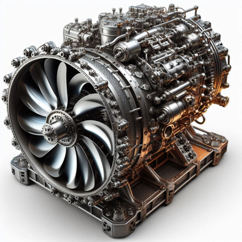
Engine Categories: Attritional vs. Long-Duration
Broadly speaking, powerplants fall into two categories: attritional and long-duration.
Attritional powerplants are designed for short service lives—often single-use or low-cycle systems intended for munitions or disposable platforms. These engines typically sacrifice performance, efficiency, and maintainability for simplicity and cost. While there have been some recent attempts to build attritional engines for UAVs, the compromises they require often limit their value outside highly specialized use cases.
In contrast, long-duration powerplants—those found in manned or reusable systems—are built for sustained use, regular maintenance, and higher performance. These engines are often more complex and expensive but offer reliability, efficiency, and supportability over time.
For Angels Aircraft, the focus is not on inventing a new engine but rather evaluating which existing engine concepts can be adapted to meet our goals. Unless your design philosophy places all weight on the performance corner of the trade space triangle (cost, schedule, technology), collaborating with an existing engine manufacturer—or using a derivative of a proven engine—is almost always the right path forward.
Integration and Influence on Design
Once a powerplant is selected, it becomes a major input into the vehicle’s structure and layout. The engine’s weight, thrust, and efficiency will define the required fuel volume. That fuel volume, in turn, affects structural weight and packaging.
As the vehicle matures through early design, the engine may need to iterate alongside the structure. Changes in vehicle mass, mission profile, or aerodynamic requirements can push the engine’s operating envelope, requiring further refinement. From a systems perspective, this relationship must be tightly managed to ensure balance across the platform.
Maintainability and Inspection Access
In terms of design priority, the supportability of the engine should be treated with the same importance as its integration. Powerplants often rival the rest of the airframe in cost and require frequent inspections—whether for safety, reliability, or warranty compliance.
There are two common strategies for powerplant inspections:
In-place inspection, where the engine remains installed and access is designed into the vehicle (as is common with commercial airliners).
Quick-removal architecture, where the engine is easily detached for bench or depot-level inspections.
Given the complexity of high-performance engines and the potential downtime associated with inspections, we believe the better direction for Angels Aircraft is to focus on rapid engine interchangeability. This enables high sortie rates, modular maintenance, and scalable fleet operations.
Structural Integration
Fortunately, from a structural standpoint, engines are among the more straightforward systems to integrate. Their load paths, mounting points, and isolation zones are typically well-defined by the engine manufacturer. Damping, thrust transmission, and thermal isolation requirements are established, making them easier to accommodate in the structural layout.
Where complexity does arise is in the supportability of that integration. Maintenance crews must have access to service connections, tools, and replacement paths. These considerations should be part of the structural design from day one—not as a retrofit after flight testing.
Expanding the Trade Space
Powerplant selection introduces an important fourth dimension into our traditional design trade space: downtime. In addition to cost, schedule, and technology, we must also consider how much time the engine will spend out of service over the life of the aircraft. This drives long-term operating cost and mission readiness, and it’s especially critical in high-tempo or distributed fleet operations.
This addition to the trade space will be explored further when we discuss acquisition cost vs. operating cost vs. sustainment cost. For now, it's enough to emphasize that powerplant decisions go far beyond thrust—they shape the platform’s entire lifecycle strategy.
Avionics Architecture
At Angels Aircraft, we’re pursuing a different approach to avionics architecture—one that breaks away from traditional aerospace and UAV design norms. We view the avionics system not just as a functional layer, but as the nervous system of the aircraft. It governs how intelligent, adaptable, and future-ready the platform can become.
Our philosophy is anchored on two core principles:
A fully digital thread
A decentralized computing architecture
But bringing that vision to life requires intentional support from the airframe structure itself.
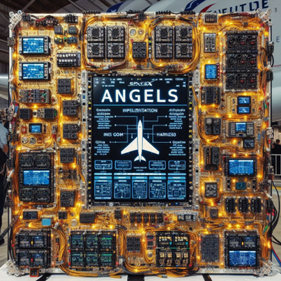
Structural Considerations for Avionics
The structural design must provide the necessary conditions for modular, accessible, and reliable avionics integration. This means strategically placing avionics near their area of operation in environmentally controlled, vibration-damped bays. These bays must offer easy access to both power and data loops, enabling streamlined connectivity and system checks.
Crucially, these modules should be designed as Line Replaceable Units (LRUs)—enabling quick swaps during maintenance or in response to in-flight reliability issues. This approach supports high-rate manufacturing by decoupling the avionics system from airframe complexity and dramatically improving serviceability.
Clear maintenance feedback loops—including install verification and environmental condition monitoring—should be integrated into these bays, reinforcing operational reliability and sustaining fleet readiness at scale.
Redundancy, Robustness, and Resilience
This architecture reshapes how we think about redundancy and fault tolerance. Traditional systems rely on physical duplication: more flight computers, more harnesses, more connectors. That’s not only expensive—it adds unnecessary weight.
In contrast, our distributed computing model offers redundancy through flexibility. Processing power is spread across the vehicle, enabling multiple, isolated instances of flight control logic. Each node can perform independent calculations, and if one fails, others take over without interruption. There’s no single point of failure—only a mesh of adaptable, fault-tolerant systems.
The result? A lighter, more robust, and far more resilient aircraft architecture that can tolerate multiple faults without compromising mission capability.
The Case for the Digital Thread
As introduced in our avionics harnessing discussion, we advocate for a system where all signals—analog or digital—are ultimately processed within a digital framework. This approach does more than simplify wiring—it unlocks the full potential of data-driven operation.
Take flight control, for example. Traditional CFD-based models help define how the aircraft moves from one state to another. But by integrating machine learning and data analytics, the flight system can begin to learn from its own behavior, adjusting its control laws to improve efficiency in real-time.
A static system will fly the aircraft. A learning system will fly it better—with agility, efficiency, and intelligent adaptation.
Digitization Enables Integration
Today, many flight-critical inputs—GPS, navigation, mission data—are already digital. Expanding the digital thread across all systems allows for seamless data fusion, cross-platform communication, and rapid software-based updates.
With a digital backbone, changing mission requirements no longer demand hardware swaps. Encryption protocols, targeting logic, or sensor inputs can be updated with a software patch, not a hardware rebuild. This mirrors the leap from the flip phone to the iPhone—not just smarter hardware, but a smarter platform, continually evolving through software.
From Centralized to Decentralized Computing
Most legacy aircraft rely on a central flight computer, relegating other processors to passive roles. But nearly every vehicle already houses multiple computational nodes—sensor packages, mission computers, environmental processors—all capable of more than just sitting idle.
We see this as a missed opportunity.
Our vision is to network all of these processors together into a shared digital data loop, creating a distributed computing ecosystem. Each processor retains a primary task, but when needed, can contribute processing power to support navigation, communications, or mission-specific analysis.
In swarm operations, this scales dramatically. The aircraft becomes not just a node in the sky—but an active participant in a collaborative, networked intelligence, sharing processing tasks in real time.
A New Model for Autonomy
This architecture marks a decisive shift away from legacy, manned-aircraft thinking. There's no central command-and-control brain. Instead, intelligence is distributed, adaptive, and resilient—woven throughout the airframe in a way that supports autonomous operations from day one.
With distributed assets, we can run multiple, redundant instances of flight control software, enabling parallel route calculations and guidance solutions. Redundancy no longer requires redundant hardware. It’s achieved through software architecture—cutting weight, improving reliability, and enhancing mission assurance.
This is not just a new avionics architecture. It’s a new foundation for how aircraft will operate, evolve, and collaborate in the future.
As you can tell, there’s much more to unbox here. The avionics architecture isn’t just a system—it’s a strategy, a philosophy, and a foundation for the future of autonomous flight. We’ve only scratched the surface, and many of these ideas—like decentralized processing, software-defined upgrades, and swarm-based intelligence—deserve a deeper dive.
We’ll be exploring all of that in an upcoming post dedicated entirely to Avionics
Architecture.
GSE and Ground Support
While the aircraft is designed to operate in the air, the truth is that it spends the majority of its lifecycle on the ground—between sorties, waiting for missions, undergoing maintenance, or simply being stored. For that reason, ground interaction becomes one of the most important aspects of aircraft design. This includes everything from fueling, inspecting, and checking avionics to transporting, storing, and conditioning the vehicle for its next flight. In most operational environments, these tasks are highly repetitive and standardized. Therefore, they should be designed to be performed quickly, consistently, and with as little hands-on interaction as possible.
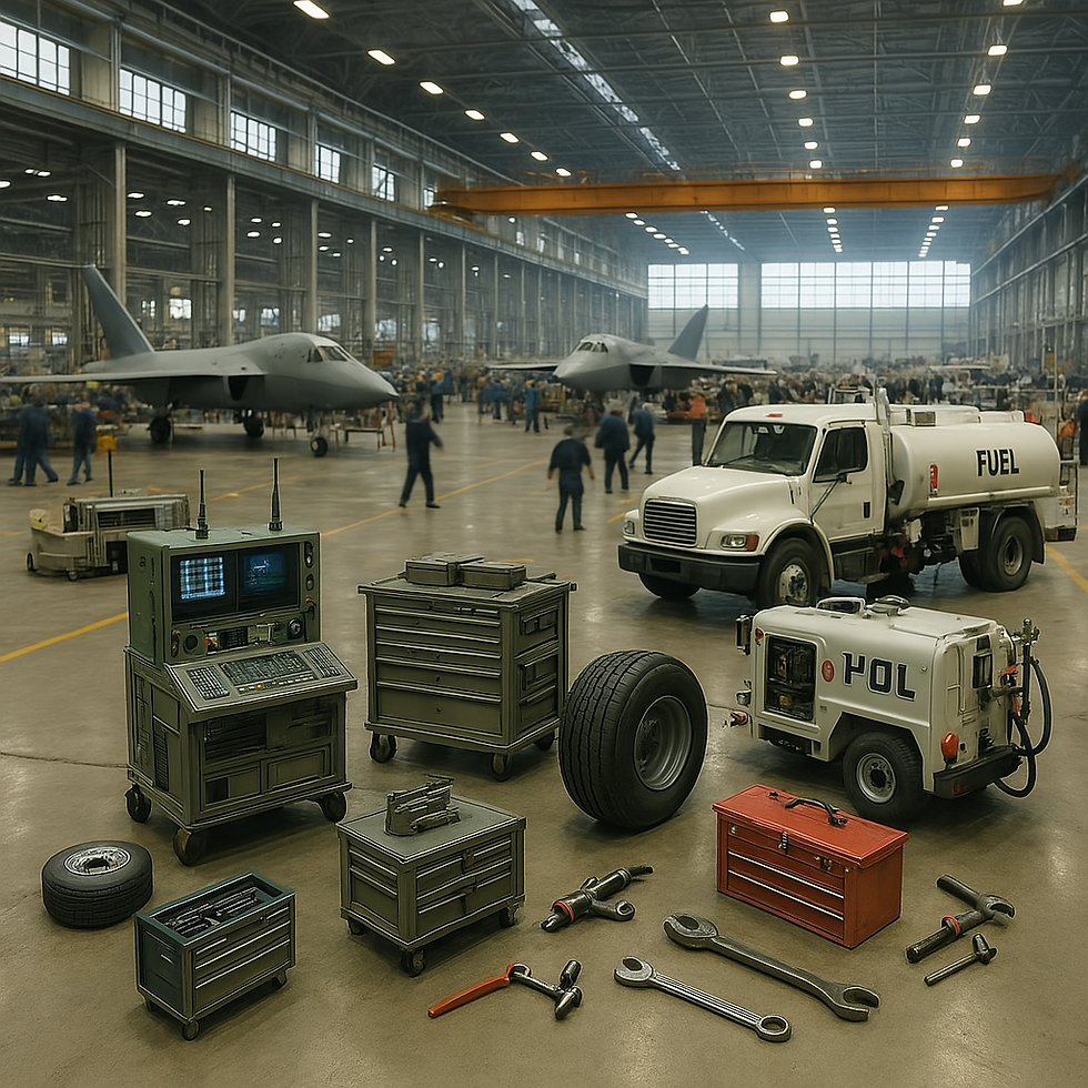
At Angels Aircraft, we believe that designing for ground support efficiency is just as important as designing for flight performance. From the outset, the aircraft must be structured to support these recurring actions with minimal complexity. Avionics bays should be accessible and environmentally controlled, allowing for quick diagnostics and LRU (Line Replaceable Unit) swaps. Refueling ports, inspection points, and servicing access should be positioned logically, with clear and repeatable procedures to minimize maintainer workload. The goal is to make the aircraft easy to work on—especially in distributed, remote, or austere environments where every second of downtime adds cost and reduces operational readiness.
This emphasis on ground support is not just a cost-saving measure, though it certainly reduces the need for highly trained personnel to be deployed globally. It’s also a method for increasing platform reliability and predictability. When maintenance tasks are designed to be carried out the same way every time, with fewer human variables in play, errors go down and system availability goes up. Every part of the aircraft—from the engines to the avionics harnessing to the fluid systems—should be designed with these support workflows in mind.
Another critical layer of ground support design is in diagnostics and fleet monitoring. It’s not enough to physically inspect the aircraft; we should be able to observe and understand how it's performing in the broader context of the fleet. Structurally, this means building in provisions for embedded sensing—accelerometers, environmental monitors, or even excitation-response systems that can provide real-time feedback about the condition of the airframe. And on the software side, it means building a data infrastructure that allows us to compare one vehicle’s performance to another’s.
Rather than modeling every possible failure mode for every aircraft, we can take a smarter approach by looking for deviations. If one platform consistently runs hotter, vibrates more, or draws more power than others in the fleet under the same conditions, that anomaly becomes the basis for investigation. This doesn’t just reduce diagnostic burden—it makes maintenance smarter and more targeted.
I once worked on a rotorcraft program that applied this exact methodology. We used the vibration profiles of the engine, main rotor, and tail rotor to assess the structural integrity of the aircraft over time. By comparing the vibrational response across the composite airframe, we could detect whether parts were loosening, degrading, or even failing—without ever needing to open up the structure. This method provided us with a non-intrusive, data-driven way of understanding when a platform was beginning to diverge from its baseline or from the fleet norm.
These types of diagnostic systems are key to long-term maintenance efficiency. Rather than relying on additional sensors and wiring solely for troubleshooting, we can leverage the vehicle’s normal operating behavior to identify when and where intervention is needed. This not only improves readiness but also helps reduce weight and complexity by minimizing the need for purpose-built diagnostic hardware.
In short, the way a vehicle is supported on the ground should be treated as a fundamental design concern, not an afterthought. It impacts cost, operational tempo, platform longevity, and mission success. And in the era of scalable, autonomous systems, designing for smart, repeatable, and data-driven ground support is just as important as flight dynamics or structural performance.

Closing Thoughts: Why Structure Comes First
In the conceptual design of a composite aircraft, structure isn’t just one consideration among many—it’s the foundation upon which everything else is built. The structure defines the physical framework, the load paths, the integration zones, and the constraints that every other system—avionics, propulsion, fluids, mission payload—must work within. Starting with structure ensures that the vehicle is not only aerodynamically viable and operationally effective, but also manufacturable, maintainable, and scalable.
In composite design especially, structure carries even more influence. Composites allow for optimized, integrated geometries and high strength-to-weight ratios—but only when structural decisions are made early, with manufacturing and system integration in mind. Waiting to solve structural challenges downstream often leads to compromises in weight, complexity, and cost.
By putting structure at the center of early design, we create a natural framework for trade studies, system routing, thermal planning, and modular upgrades. We enable smarter decisions, earlier. And we build a foundation that’s light, strong, scalable—and ready to evolve with the mission.


Comments